एलिमेंट लाइब्रेरी
FrontISTR में विश्लेषण मॉडल की ज्यामिति, governing equations और आवश्यक स्वतंत्रता-कोटियों के अनुसार line, plane, solid, interface, beam और shell elements का उपयोग किया जाता है। यह पृष्ठ element चयन के लिए आवश्यक बातों को व्यवस्थित करता है: किस विश्लेषण में कौन-सा element उपयोग किया जा सकता है, first-order solid element की formulation कैसे चुनी जाए, structural और solid elements को कैसे मिलाया जाए, तथा structural contact में किन element faces का उपयोग किया जा सकता है।
इनपुट कीवर्ड की विशिष्ट syntax के लिए keyword reference देखें। shape functions, stiffness matrices और locking से बचने की विधियों की गणितीय व्युत्पत्ति theory manual में दी गई है।
एलिमेंट लाइब्रेरी का अवलोकन
वर्तमान FrontISTR स्रोत में elements को मोटे तौर पर line, plane, solid, interface, beam और shell categories में बाँटा जा सकता है। continuum को सीधे discretize करने के लिए plane या solid elements चुनें, जबकि slender members या thin-walled structures को कुशलतापूर्वक दर्शाने के लिए beam या shell elements चुनें। thermal analysis में समान geometric category के elements भी structural analysis से अलग assembly path लेते हैं, इसलिए उपलब्ध elements की पुष्टि हमेशा नीचे की तालिका से करनी चाहिए।
Element type number सामान्यतः 3 अंकों का होता है। पहला अंक व्यापक element category दर्शाता है और शेष 2 अंक geometry और series को अलग करते हैं। उदाहरण के लिए 231/232 triangular plane first-/second-order series, 341/342 tetrahedral first-/second-order series और 361/362 hexahedral first-/second-order series हैं। लेकिन 301 एक 2-node truss element और 743 एक 9-node shell element है, इसलिए हर series को केवल “अंतिम अंक 1 = first order, 2 = second order” नियम से नहीं समझा जा सकता। केवल संख्या से यांत्रिक निष्कर्ष न निकालें; नीचे की तालिकाओं से पुष्टि करें।
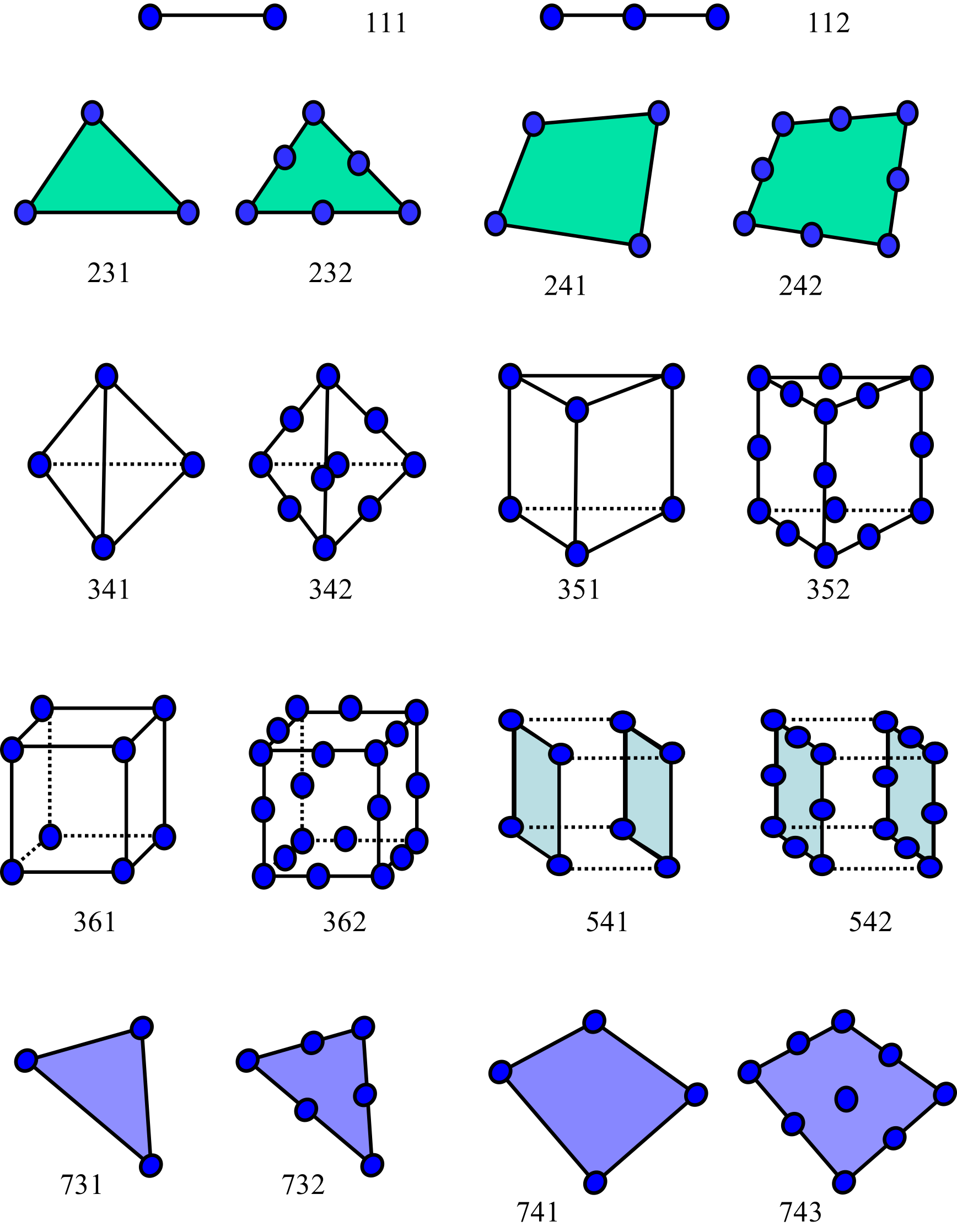
तालिकाओं में चिह्नों का अर्थ निम्न है।
○: समर्थित।—: समर्थित नहीं।
यहाँ “गतिशील” से transient dynamic analysis और “मोडल” से modal analysis तथा frequency response analysis के आधार के रूप में प्रयुक्त mode calculation अभिप्रेत है। Thermal कॉलम में केवल heat conduction analysis में उपयोग योग्य elements को ○ से चिह्नित किया गया है।
Continuum और interface elements
| Element श्रेणी | Element type | Nodes | Structural DOFs/node | Thermal DOFs/node | ज्यामिति / क्रम | Stress | गतिशील | मोडल | Thermal | Formulation / टिप्पणियाँ |
|---|---|---|---|---|---|---|---|---|---|---|
| Line element | 111 | 2 | — | 1 | 2-node line element | — | — | — | ○ | heat conduction के लिए 1D element |
| Line element | 112 | 3 | — | — | 3-node line element | — | — | — | — | वर्तमान analysis functions में समर्थित नहीं |
| Plane element | 231 | 3 | 3 | 1 | first-order triangular element | ○ | ○ | ○ | ○ | 2D continuum |
| Plane element | 232 | 6 | 3 | 1 | second-order triangular element | ○ | ○ | ○ | ○ | 2D continuum |
| Plane element | 241 | 4 | 3 | 1 | first-order quadrilateral element | ○ | ○ | ○ | ○ | 2D continuum |
| Plane element | 242 | 8 | 3 | 1 | second-order quadrilateral element | ○ | ○ | ○ | ○ | Serendipity family |
| Solid element | 301 | 2 | 3 | 1 | 2-node truss element | ○ | ○ | ○ | — | numbering convention का अपवाद; thermal analysis में समर्थित नहीं |
| Solid element | 341 | 4 | 3 | 1 | first-order tetrahedral element | ○ | ○ | ○ | ○ | full integration, selective edge/node smoothing |
| Solid element | 342 | 10 | 3 | 1 | second-order tetrahedral element | ○ | ○ | ○ | ○ | |
| Solid element | 351 | 6 | 3 | 1 | first-order pentahedral element | ○ | ○ | ○ | ○ | |
| Solid element | 352 | 15 | 3 | 1 | second-order pentahedral element | ○ | ○ | ○ | ○ | |
| Solid element | 361 | 8 | 3 | 1 | first-order hexahedral element | ○ | ○ | ○ | ○ | full integration, B-bar, incompatible, F-bar, u-p mixed |
| Solid element | 362 | 20 | 3 | 1 | second-order hexahedral element | ○ | ○ | ○ | ○ | Serendipity family |
| Connector element | 511 | 2 | 3 | — | 2-node connector element | ○ | ○ | ○ | — | spring/dashpot के लिए; mass matrix नहीं है |
| Interface element | 541 | 4×2 | — | 1 | first-order quadrilateral surface element | — | — | — | ○ | gap heat transfer और radiation के लिए; capacity matrix नहीं है |
| Interface element | 542 | 8×2 | — | — | second-order quadrilateral surface element | — | — | — | — | समर्थित नहीं |
संरचनात्मक elements
| Element श्रेणी | Element type | Nodes | Structural DOFs/node | Thermal DOFs/node | ज्यामिति / क्रम | Stress | गतिशील | मोडल | Thermal | Formulation / टिप्पणियाँ |
|---|---|---|---|---|---|---|---|---|---|---|
| Beam element | 611 | 2 | 6 | 1 | 2-node beam element | ○ | ○ | ○ | — | Bernoulli-Euler beam; thermal analysis में समर्थित नहीं |
| Beam element | 641 | 2×2 | 3 | 1 | 2-node beam element (mixed DOFs के लिए) | ○ | ○ | ○ | — | Bernoulli-Euler beam; thermal analysis में समर्थित नहीं |
| Shell element | 731 | 3 | 6 | 1 | first-order triangular element | ○ | ○ | ○ | ○ | MITC3 |
| Shell element | 732 | 6 | — | — | second-order triangular element | — | — | — | — | वर्तमान analysis functions में समर्थित नहीं |
| Shell element | 741 | 4 | 6 | 1 | first-order quadrilateral element | ○ | ○ | ○ | ○ | MITC4 |
| Shell element | 743 | 9 | 6 | — | second-order quadrilateral element | ○ | ○ | ○ | — | MITC9 |
| Shell element | 761 | 3×2 | 3 | — | first-order triangular element (mixed DOFs के लिए) | ○ | ○ | ○ | — | MITC3; solid के साथ mixed DOFs के लिए |
| Shell element | 781 | 4×2 | 3 | — | first-order quadrilateral element (mixed DOFs के लिए) | ○ | ○ | ○ | — | MITC4; solid के साथ mixed DOFs के लिए |
- first-order solid elements 341 और 361 में formulation options हैं, इसलिए समान geometry के लिए भी कई विकल्प उपलब्ध हैं।
- structural analysis में contact उपयोग करने पर second-order elements की contact surfaces समर्थित नहीं हैं।
- structural elements 611/731/741/743 में 6-DOF nodes होते हैं और इन्हें solid elements के साथ सीधे नहीं मिलाया जा सकता। मिश्रित मॉडल के लिए 641/761/781 उपयोग करें।
- Beam element 611 thermal stress, gravity, pressure या centrifugal force वाले analysis को समर्थन नहीं देता। Beam element 641 pressure और centrifugal force वाले analysis को समर्थन नहीं देता।
- linear dynamic analysis में shell elements 731/741/743 के साथ parallel computation समर्थित नहीं है। अन्य elements के साथ parallel computation उपयोग किया जा सकता है।
Formulation options का चयन
first-order solid elements में geometry के साथ formulation भी चयन का विषय है। विशेष रूप से first-order hexahedral element 361 में समस्या की प्रकृति के अनुसार 4 प्रकार की formulations चुनने की implementation है। first-order tetrahedral element 341 में smoothed FEM का विकल्प भी है। दोनों को इनपुट में !SECTION के FORM341 और FORM361 से बदला जाता है।
First-order hexahedral element (361)
वर्तमान स्रोत में FORM361 के लिए FI, BBAR, IC, FBAR, UP में से 5 विकल्प चुने जा सकते हैं। FORM361 छोड़ने पर default analysis type के अनुसार बदलता है: small-deformation static और transient dynamic analysis में IC, उन्हीं के large-deformation मामलों में FBAR, modal analysis में IC, और अन्य मामलों में FI सेट होता है (UP केवल स्पष्ट रूप से निर्दिष्ट करने पर सक्रिय होता है)।
FI: मानक fully integrated element। bending में shear locking और लगभग incompressible deformation में volumetric locking से आसानी से प्रभावित होता है, इसलिए element performance की तुलना के baseline के रूप में उपयोग किया जाता है।IC: incompatible modes जोड़ने वाली formulation। bending-dominated समस्याओं में shear locking दबाने का पहला विकल्प है और linear small-deformation analysis में default है।BBAR: volumetric strain component को सुधारने वाला B-bar element, जो volumetric locking प्रधान समस्याओं के लिए उपयुक्त है। लगभग incompressible rubber-like materials या उच्च Poisson ratio वाली materials में विचार योग्य है, लेकिन volumetric strain गणना में linearity मानने के कारण finite rotation को ध्यान में नहीं रख सकता। सामान्यतः F-Bar element के उपयोग की अनुशंसा की जाती है।FBAR: deformation gradient के volumetric component को सुधारने वाला F-bar element। large deformation और मजबूत incompressibility प्रभाव वाली समस्याओं के लिए उपयुक्त है और large-deformation analysis में default है।UP: displacement और element pressure को स्वतंत्र रूप सेसंभालने वाला u-p mixed element। stress को deviatoric component और pressure में विभाजित करके लगभग incompressible materials (जैसे Poisson ratio 0.5 के अत्यंत निकट rubber-like materials या plastic deformation के बाद metals) में volumetric locking से बचता है। प्रति element 1 pressure DOF होता है, जो element के भीतर स्थिर रहता है और element level पर statically condensed किया जाता है। small deformation, Total Lagrange और Updated Lagrange समर्थित हैं।
यदि formulation चयन में संदेह हो, तो practical starting point के रूप में small-deformation structural analysis में IC, large deformation या hyperelasticity में FBAR उपयोग करें; यदि shear locking मुख्य समस्या है तो IC से तुलना करें। near-incompressibility प्रधान हो और pressure field को स्पष्ट रूप सेसंभालना हो तो UP पर विचार करें। विस्तृत theoretical background के लिए theory manual देखें।
First-order tetrahedral element (341)
वर्तमान स्रोत में FORM341 के लिए FI और SELECTIVE_ESNS चुने जा सकते हैं। default हमेशा FI है। SELECTIVE_ESNS चुनने पर setup के समय smoothed-element connectivity अतिरिक्त रूप से बनाई जाती है और इसे selective edge/node-smoothed FEM के रूप मेंसंभाला जाता है।
FI: मानक first-order tetrahedral element। मेश बनाना आसान है, लेकिन bending में shear locking और लगभग incompressible conditions में volumetric locking से प्रभावित होने की प्रवृत्ति है।SELECTIVE_ESNS: edge-based/node-based smoothing लागू करके first-order tetrahedral elements में सामान्य shear locking और volumetric locking के प्रभाव को कम करता है। geometry constraints के कारण tetrahedra उपयोग करना अनिवार्य हो तो यह मजबूत विकल्प है।
यदि geometric कारणों से 341 उपयोग करना आवश्यक हो और standard FI में locking का प्रभाव अधिक हो, तो SELECTIVE_ESNS पर विचार करें। इसके विपरीत, यदि first-order hexahedral elements उपयोग किए जा सकते हों, तो 361 series में पहले IC/BBAR/FBAR पर विचार करना सामान्यतः अधिक विकल्प देता है।
MPI parallelism में SELECTIVE_ESNS उपयोग करते समय domain decomposition की overlap depth पर ध्यान दें। edge-based/node-based smoothing लक्ष्य element के adjacent elements की quantities का औसत लेता है, इसलिए subdomain में element stiffness assemble करने हेतु “पड़ोसी के पड़ोसी” element की जानकारी चाहिए। default overlap depth 1 में domain boundary के पास पर्याप्त smoothing targets नहीं मिलते; इसलिए domain decomposition करते समय !PARTITION में DEPTH=2 निर्दिष्ट करें। विवरण के लिए domain decomposition की overlap depth देखें।
Structural और solid elements का संयुक्त उपयोग
समान “beam element” या “shell element” में भी structural और thermal analysis में DOF handling अलग है। इसलिए solid elements के साथ संयुक्त उपयोग के नियम भी दोनों में समान नहीं हैं।
संरचनात्मक विश्लेषण
structural analysis में पूरे analysis के लिए nodal DOF count ndof एक मान पर स्थिर होता है। solid elements में प्रति node 3 DOFs (translation) होते हैं, जबकि standard beam element 611 और shell elements 731/741/743 में प्रति node 6 DOFs (translation + rotation) होते हैं। इसलिए 611, 731, 741, 743 को solid elements के साथ सीधे उसी nodal-DOF system में नहीं मिलाया जा सकता।
इस प्रतिबंध से बचने के लिए 3-DOF-node versions 641, 761, 781 उपलब्ध हैं। translation DOF वाले nodes और rotation DOF वाले nodes को अलग रखकर ये elements पूरे analysis में ndof=3 बनाए रखते हुए beam/shell rotational DOFs दर्शाते हैं। संबंध निम्न हैं।
- 641, 611 के अनुरूप mixed-DOF beam element है।
- 761, 731 के अनुरूप mixed-DOF triangular shell element है।
- 781, 741 के अनुरूप mixed-DOF quadrilateral shell element है।
mixed-DOF elements में rotational DOFs स्वतंत्र “rotational DOF वाले nodes” को दिए जाते हैं। इसलिए constraints या concentrated loads देते समय उन्हें उन rotational nodes की DOFs 1, 2, 3 के रूप में दर्ज करना होता है। translational nodes की DOFs 1, 2, 3 और rotational nodes की DOFs 1, 2, 3 को अलग node identity से पहचाना जाता है।
अतः केवल beams/shells से मॉडल बनाने पर 611/731/741/743 उपयोग करें और solid elements के साथ उपयोग करने पर 641/761/781 चुनें।
Thermal analysis
thermal analysis में hecMAT%NDOF = 1 सेट होता है और nodal DOF तापमान की एक स्वतंत्रता-कोटि पर एकीकृत होता है। इस अर्थ में structural analysis की “3-DOF-node version के बिना elements नहीं मिल सकते” वाली समस्या उत्पन्न नहीं होती।
हालाँकि thermal analysis में समर्थित structural elements केवल 731 और 741 हैं। 611, 641 और 301 thermal analysis में समर्थित नहीं हैं। इसलिए thermal analysis के लिए element चुनते समय structural mixed-DOF अवधारणा के बजाय पिछली तालिका के Thermal कॉलम में ○ चिह्नित elements को आधार बनाना सुरक्षित है।
Connector elements (springs और dashpots)
यदि दो nodes को discrete spring या dashpot से जोड़ना हो तो 2-node connector element (element type 511) उपयोग करें। connector element जुड़े दो nodes के बीच केवल stiffness या damping देता है; उसमें geometry, cross section या mass नहीं होता।
Connector element कुल चार characteristics दर्शा सकता है: springs के दो प्रकार और dashpots के दो प्रकार। कौन-सा characteristic होगा, यह element को assigned material से तय होता है।
- Axial spring — दो nodes को जोड़ने वाली axial direction में कार्य करने वाला spring। spring की दिशा model deformation का अनुसरण करती है। इनपुट में
!SPRING_Aसे दिया जाता है। - Specified-DOF spring — एक node की निर्दिष्ट DOF को दूसरे node की निर्दिष्ट DOF से जोड़ने वाला spring। दिशा DOF numbers से निर्धारित होती है और deformation का अनुसरण नहीं करती। प्रत्येक दिशा के लिए अलग spring constant दिया जा सकता है। इनपुट में
!SPRING_Dसे दिया जाता है। - Axial dashpot — axial direction में कार्य करने वाला damping। इनपुट में
!DASHPOT_Aसे दिया जाता है। - Specified-DOF dashpot — निर्दिष्ट DOFs को जोड़ने वाला damping। इनपुट में
!DASHPOT_Dसे दिया जाता है।
Springs stiffness matrix में और dashpots damping matrix में योगदान करते हैं। इसलिए spring static, dynamic और modal analyses में प्रभावी है, जबकि dashpot केवल damping matrix assemble करने वाले implicit dynamic analysis में प्रभावी है और static analysis में प्रभाव नहीं रखता।
यदि spring को दो nodes के बीच नहीं बल्कि node और ground के बीच रखना हो, तो connector element के बजाय spring boundary condition (!SPRING) उपयोग करें। यह element परिभाषित किए बिना nodal DOF को elastically support करने वाली boundary condition है।
mesh data में connector element को element type 511 के रूप में परिभाषित करें और उसके element group को section type INTERFACE वाला section दें। spring constants और damping coefficients analysis control data में material के रूप में दें। → विवरण के लिए !SPRING_A देखें।
Connectivity और face number definitions
नीचे के चित्र और तालिकाएँ HEC-MW format में input node ordering और face numbers के संबंध को दिखाती हैं। second-order elements के midside-node numbering और FrontISTR की internal shape-function implementation द्वारा अपेक्षित ordering का संबंध जानने के लिए theory manual का “Element Library” देखें।
Line elements

Triangular plane elements
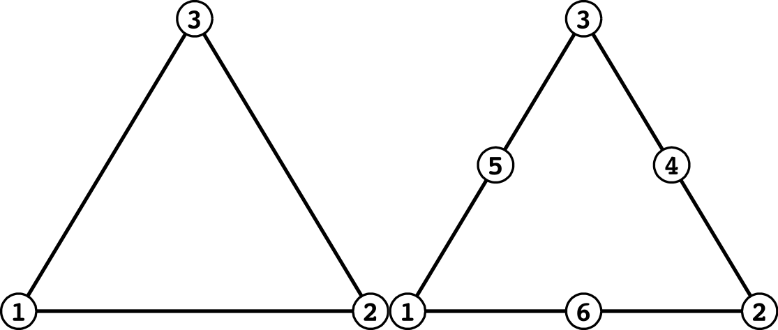
| Face number | First order | Second order |
|---|---|---|
| 1 | 1 - 2 | 1 - 6 - 2 |
| 2 | 2 - 3 | 2 - 4 - 3 |
| 3 | 3 - 1 | 3 - 5 - 1 |
Quadrilateral plane elements
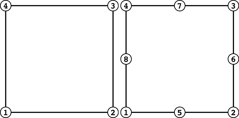
| Face number | First order | Second order |
|---|---|---|
| 1 | 1 - 2 | 1 - 5 - 2 |
| 2 | 2 - 3 | 2 - 6 - 3 |
| 3 | 3 - 4 | 3 - 7 - 4 |
| 4 | 4 - 1 | 4 - 8 - 1 |
Tetrahedral elements
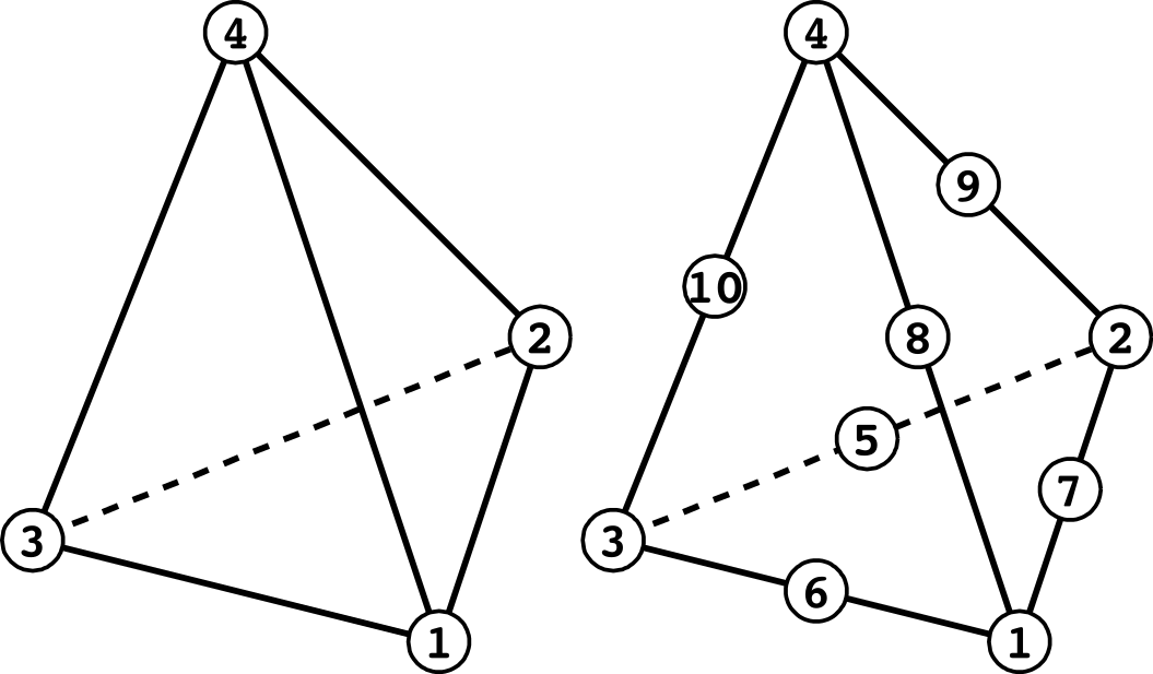
| Face number | First order | Second order |
|---|---|---|
| 1 | 1 - 2 - 3 | 1 - 7 - 2 - 5 - 3 - 6 |
| 2 | 1 - 2 - 4 | 1 - 7 - 2 - 9 - 4 - 8 |
| 3 | 2 - 3 - 4 | 2 - 5 - 3 - 10 - 4 - 9 |
| 4 | 3 - 1 - 4 | 3 - 6 - 1 - 10 - 4 - 8 |
Pentahedral elements
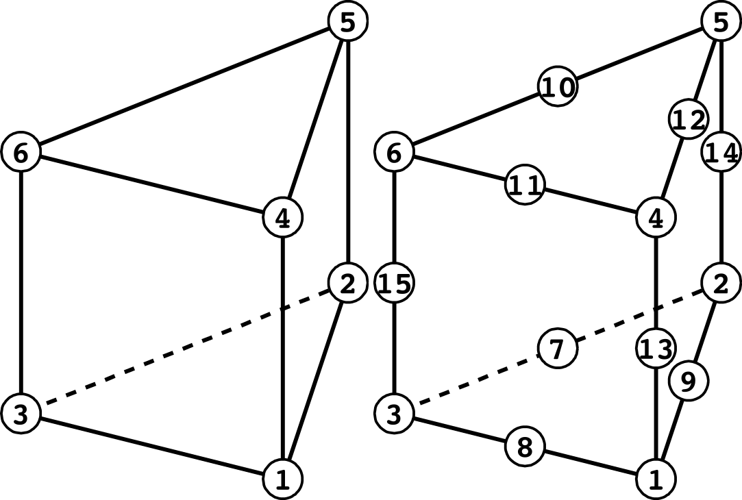
| Face number | First order | Second order |
|---|---|---|
| 1 | 1 - 2 - 3 | 1 - 9 - 2 - 7 - 3 - 8 |
| 2 | 4 - 5 - 6 | 4 - 12 - 5 - 10 - 6 - 11 |
| 3 | 1 - 2 - 5 - 4 | 1 - 9 - 2 - 14 - 5 - 12 - 4 - 13 |
| 4 | 2 - 3 - 6 - 5 | 2 - 7 - 3 - 15 - 6 - 10 - 5 - 14 |
| 5 | 3 - 1 - 4 - 6 | 3 - 8 - 1 - 13 - 4 - 11 - 6 - 15 |
Hexahedral elements
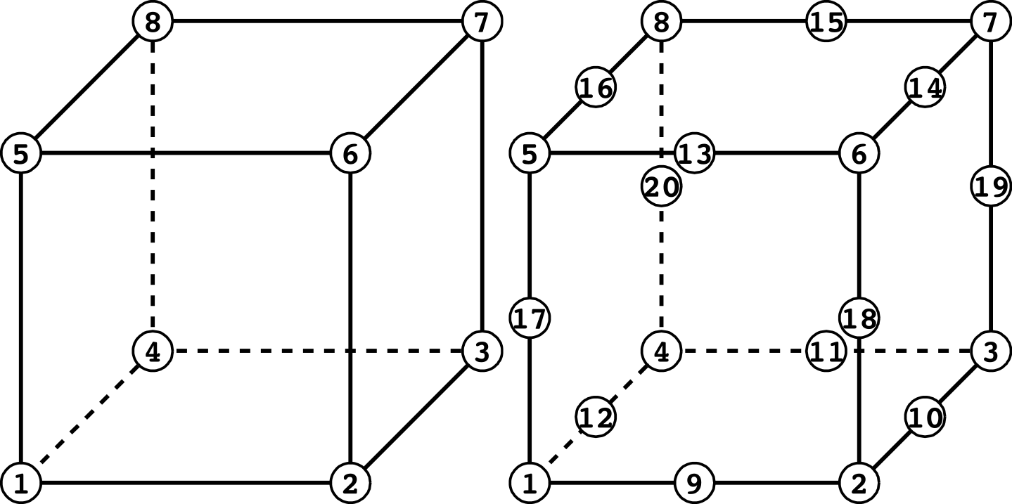
| Face number | First order | Second order |
|---|---|---|
| 1 | 1 - 2 - 3 - 4 | 1 - 9 - 2 - 10 - 3 - 11 - 4 - 12 |
| 2 | 5 - 6 - 7 - 8 | 5 - 13 - 6 - 14 - 7 - 15 - 8 - 16 |
| 3 | 1 - 2 - 6 - 5 | 1 - 9 - 2 - 18 - 6 - 13 - 5 - 17 |
| 4 | 2 - 3 - 7 - 6 | 2 - 10 - 3 - 19 - 7 - 14 - 6 - 18 |
| 5 | 3 - 4 - 8 - 7 | 3 - 11 - 4 - 20 - 8 - 15 - 7 - 19 |
| 6 | 4 - 1 - 5 - 8 | 4 - 12 - 1 - 17 - 5 - 16 - 8 - 20 |
Beam elements

3-DOF nodes वाला beam element
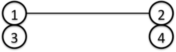
Nodes 1 और 2 में translational DOFs हैं, जबकि nodes 3 और 4 में rotational DOFs हैं।
Triangular shell elements
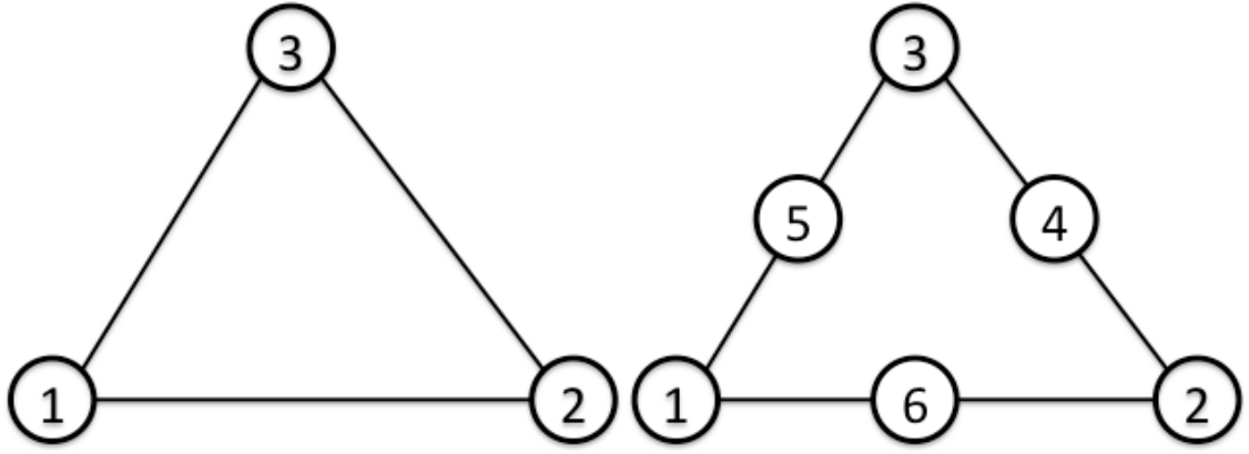
| Face number | First order | Second order |
|---|---|---|
| 1 | 1 - 2 - 3 [front] | 1 - 6 - 2 - 4 - 3 - 5 [front] |
| 2 | 3 - 2 - 1 [back] | 3 - 4 - 2 - 6 - 1 - 5 [back] |
3-DOF nodes वाला triangular shell element
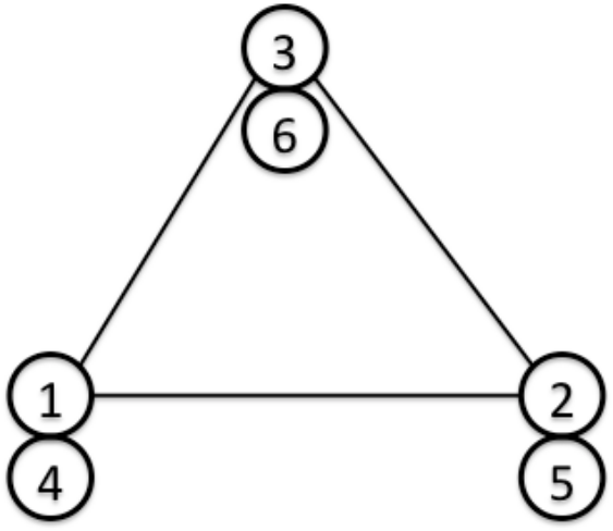
Nodes 1, 2, 3 में translational DOFs हैं, जबकि nodes 4, 5, 6 में rotational DOFs हैं।
| Face number | First order |
|---|---|
| 1 | 1 - 2 - 3 [front] |
| 2 | 3 - 2 - 1 [back] |
Quadrilateral shell elements
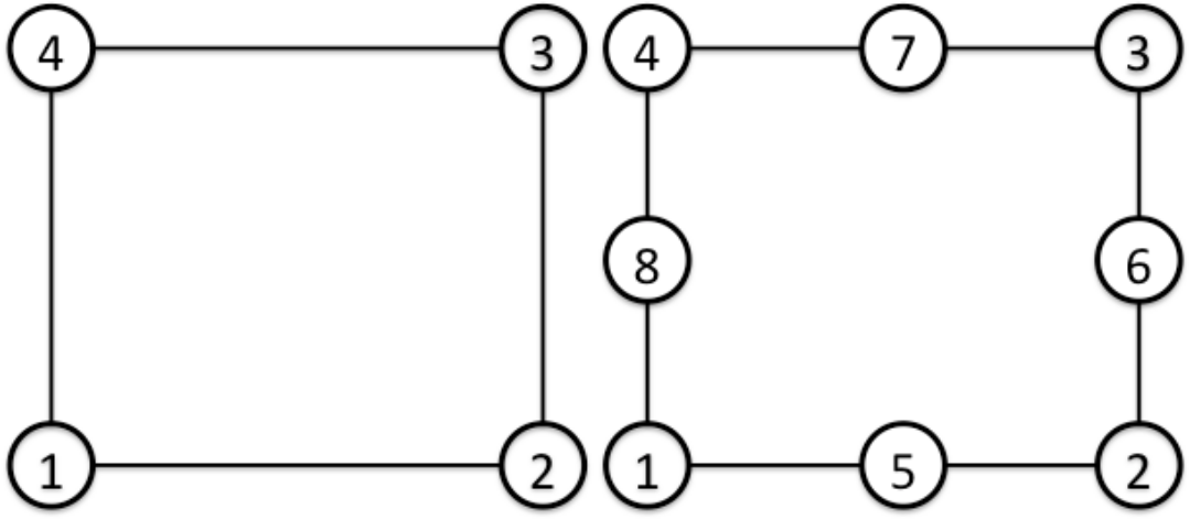
| Face number | First order | Second order |
|---|---|---|
| 1 | 1 - 2 - 3 - 4 [front] | 1 - 5 - 2 - 6 - 3 - 7 - 4 - 8 [front] |
| 2 | 4 - 3 - 2 - 1 [back] | 4 - 7 - 3 - 6 - 2 - 5 - 1 - 8 [back] |
3-DOF nodes वाला quadrilateral shell element
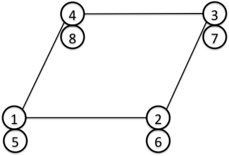
Nodes 1, 2, 3, 4 में translational DOFs हैं, जबकि nodes 5, 6, 7, 8 में rotational DOFs हैं।
| Face number | First order |
|---|---|
| 1 | 1 - 2 - 3 - 4 [front] |
| 2 | 4 - 3 - 2 - 1 [back] |
संबंधित विषय
- Element numbering system और shape-function library (coding) — element type numbers, shape-function library और midside-node ordering specifications
- सामग्री डेटा — elements को assigned material models
!ELEMENT— element-definition keyword की syntax!SECTION(मेश डेटा) — element type, material, thickness और section का विनिर्देशन!SECTION(विश्लेषण नियंत्रण डेटा) —FORM341औरFORM361से formulation switching