Element Library
FrontISTR uses line, plane, solid, interface, beam, and shell elements according to the geometry of the analysis target, the governing equations, and the required degrees of freedom. This page summarizes the information needed when selecting elements: which elements are available for each analysis type, how to choose formulations for first-order solid elements, how to combine structural elements with solid elements, and which element faces can be used for contact in structural analysis.
For the specific syntax of input keywords, see the keyword reference. Mathematical derivations of shape functions, stiffness matrices, and locking-avoidance methods are covered in the theory manual.
Overview of the Element Library
The element categories handled by the current FrontISTR source can be broadly classified as line, plane, solid, interface, beam, and shell elements. Use plane or solid elements when discretizing a continuum directly, and beam or shell elements when efficiently representing slender members or thin-walled structures. In thermal analysis, even elements in the same geometric category follow a different assembly path from structural analysis, so the available elements should always be checked in the table below.
Element type numbers are generally three digits. The first digit indicates the broad element category, while the remaining two distinguish the geometry and series. For example, 231/232 are the first-/second-order triangular plane series, 341/342 the first-/second-order tetrahedral series, and 361/362 the first-/second-order hexahedral series. However, as shown by 301 being a 2-node truss element and 743 being a 9-node shell element, not every series follows a simple rule such as "last digit 1 = first order, 2 = second order." Do not infer the element mechanically from the number alone; confirm it in the following tables.
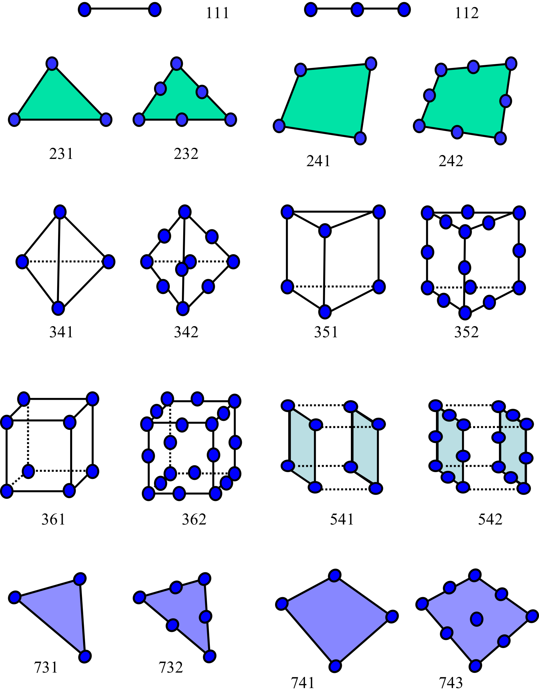
The symbols in the tables have the following meanings.
○: Supported.—: Not supported.
Here, "Dynamic" means transient dynamic analysis, and "Modal" means the mode calculation used for modal analysis and as the basis for frequency response analysis. In the Thermal column, only elements available for heat conduction analysis are marked ○.
Continuum and Interface Elements
| Element category | Element type | Nodes | Structural DOFs/node | Thermal DOFs/node | Geometry / order | Stress | Dynamic | Modal | Thermal | Formulation / Notes |
|---|---|---|---|---|---|---|---|---|---|---|
| Line element | 111 | 2 | — | 1 | 2-node line element | — | — | — | ○ | 1D element for heat conduction |
| Line element | 112 | 3 | — | — | 3-node line element | — | — | — | — | Not supported by the current analysis functions |
| Plane element | 231 | 3 | 3 | 1 | First-order triangular element | ○ | ○ | ○ | ○ | 2D continuum |
| Plane element | 232 | 6 | 3 | 1 | Second-order triangular element | ○ | ○ | ○ | ○ | 2D continuum |
| Plane element | 241 | 4 | 3 | 1 | First-order quadrilateral element | ○ | ○ | ○ | ○ | 2D continuum |
| Plane element | 242 | 8 | 3 | 1 | Second-order quadrilateral element | ○ | ○ | ○ | ○ | Serendipity family |
| Solid element | 301 | 2 | 3 | 1 | 2-node truss element | ○ | ○ | ○ | — | Exception to the numbering convention; not supported for thermal analysis |
| Solid element | 341 | 4 | 3 | 1 | First-order tetrahedral element | ○ | ○ | ○ | ○ | Full integration; selective edge-/node-based smoothing |
| Solid element | 342 | 10 | 3 | 1 | Second-order tetrahedral element | ○ | ○ | ○ | ○ | |
| Solid element | 351 | 6 | 3 | 1 | First-order pentahedral element | ○ | ○ | ○ | ○ | |
| Solid element | 352 | 15 | 3 | 1 | Second-order pentahedral element | ○ | ○ | ○ | ○ | |
| Solid element | 361 | 8 | 3 | 1 | First-order hexahedral element | ○ | ○ | ○ | ○ | Full integration, B-bar, incompatible, F-bar, u-p mixed |
| Solid element | 362 | 20 | 3 | 1 | Second-order hexahedral element | ○ | ○ | ○ | ○ | Serendipity family |
| Interface element | 541 | 4×2 | — | 1 | First-order quadrilateral surface element | — | — | — | ○ | For gap heat transfer and radiation; has no capacity matrix |
| Interface element | 542 | 8×2 | — | — | Second-order quadrilateral surface element | — | — | — | — | Not supported |
Structural Elements
| Element category | Element type | Nodes | Structural DOFs/node | Thermal DOFs/node | Geometry / order | Stress | Dynamic | Modal | Thermal | Formulation / Notes |
|---|---|---|---|---|---|---|---|---|---|---|
| Beam element | 611 | 2 | 6 | 1 | 2-node beam element | ○ | ○ | ○ | — | Bernoulli-Euler beam; not supported for thermal analysis |
| Beam element | 641 | 2×2 | 3 | 1 | 2-node beam element (for mixed DOFs) | ○ | ○ | ○ | — | Bernoulli-Euler beam; not supported for thermal analysis |
| Shell element | 731 | 3 | 6 | 1 | First-order triangular element | ○ | ○ | ○ | ○ | MITC3 |
| Shell element | 732 | 6 | — | — | Second-order triangular element | — | — | — | — | Not supported by the current analysis functions |
| Shell element | 741 | 4 | 6 | 1 | First-order quadrilateral element | ○ | ○ | ○ | ○ | MITC4 |
| Shell element | 743 | 9 | 6 | — | Second-order quadrilateral element | ○ | ○ | ○ | — | MITC9 |
| Shell element | 761 | 3×2 | 3 | — | First-order triangular element (for mixed DOFs) | ○ | ○ | ○ | — | MITC3; for mixed DOFs with solids |
| Shell element | 781 | 4×2 | 3 | — | First-order quadrilateral element (for mixed DOFs) | ○ | ○ | ○ | — | MITC4; for mixed DOFs with solids |
- Among first-order solid elements, 341 and 361 have formulation options, so multiple choices are available even for the same geometry.
- When contact is used in structural analysis, contact surfaces of second-order elements are not supported.
- Structural elements 611/731/741/743 use 6-DOF nodes and cannot be mixed directly with solid elements. Use 641/761/781 for mixed models.
- Beam element 611 does not support analyses including thermal stress, gravity, pressure, or centrifugal force. Beam element 641 does not support analyses including pressure or centrifugal force.
- In linear dynamic analysis, parallel computation is not supported when shell elements 731/741/743 are used. Parallel computation can be used with the other elements.
Choosing Formulation Options
For first-order solid elements, the formulation is a selection criterion in addition to the geometry. In particular, first-order hexahedral element 361 is implemented so that four types of formulations can be selected according to the characteristics of the problem. First-order tetrahedral element 341 also provides a smoothed FEM option. In both cases, use !SECTION with FORM341 or FORM361 to select the formulation.
First-Order Hexahedral Element (361)
In the current source, FORM361 can be set to one of five options: FI, BBAR, IC, FBAR, or UP. If FORM361 is omitted, the default depends on the analysis type: IC for small-deformation static and transient dynamic analysis, FBAR for large-deformation static and transient dynamic analysis, IC for modal analysis, and FI otherwise (UP is enabled only when specified explicitly).
FI: Standard fully integrated element. It is susceptible to shear locking in bending and volumetric locking in nearly incompressible deformation, so it is mainly useful as a baseline for comparing element performance.IC: Formulation with incompatible modes. It is the first choice when suppressing shear locking in bending-dominated problems and is the default for linear small-deformation analysis.BBAR: B-bar element that corrects the volumetric strain component and is suited to problems dominated by volumetric locking. It can be considered for nearly incompressible rubber-like materials or materials with a high Poisson ratio, but because the volumetric-strain calculation assumes linearity, finite rotation cannot be taken into account. Use of the F-Bar element is generally recommended.FBAR: F-bar element that corrects the volumetric component of the deformation gradient. It is suited to large-deformation problems with strong incompressibility effects and is the default for large-deformation analysis.UP: u-p mixed element that treats displacement and element pressure independently. It separates stress into deviatoric and pressure components to avoid volumetric locking in nearly incompressible materials, such as rubber-like materials with Poisson's ratio extremely close to 0.5 or metals after plastic deformation. There is one pressure degree of freedom per element (constant within the element), which is statically condensed at the element level. Small-deformation, Total Lagrange, and Updated Lagrange formulations are supported.
If uncertain which formulation to use, a practical starting point is IC for small-deformation structural analysis and FBAR for large deformation or hyperelasticity; if shear locking is the primary issue, compare with IC. If near-incompressibility dominates and the pressure field is to be treated explicitly, consider UP. See the theory manual for the detailed theoretical background.
First-Order Tetrahedral Element (341)
In the current source, FORM341 can be set to FI or SELECTIVE_ESNS. The default is always FI. When SELECTIVE_ESNS is selected, connectivity for smoothed elements is additionally generated during setup, and the element is treated using selective edge-/node-smoothed FEM.
FI: Standard first-order tetrahedral element. Meshing is easy, but the element is susceptible to shear locking in bending and volumetric locking under nearly incompressible conditions.SELECTIVE_ESNS: Introduces edge-based/node-based smoothing to reduce the shear-locking and volumetric-locking effects that readily appear in first-order tetrahedral elements. This is a strong option when geometric constraints require the use of tetrahedra.
If element 341 must be used for geometric reasons and locking is significant with the standard FI, consider SELECTIVE_ESNS. Conversely, if first-order hexahedral elements can be used, the 361 series generally provides a broader range of choices, so first consider IC/BBAR/FBAR.
When using SELECTIVE_ESNS with MPI parallelism, pay attention to the overlap depth during domain decomposition. Edge-based/node-based smoothing averages quantities from elements adjacent to the target element, so assembling element stiffness within a subdomain requires information from elements two adjacency levels away. With the default overlap depth of 1, insufficient smoothing targets are available near domain boundaries; therefore, in !PARTITION, specify DEPTH=2 when decomposing the domain. For configuration details, see Overlap Depth in Domain Decomposition.
Combining Structural and Solid Elements
Even for the same "beam element" or "shell element," degrees of freedom are handled differently in structural and thermal analyses. Consequently, the rules for combining them with solid elements are also different.
Structural Analysis
In structural analysis, the number of nodal degrees of freedom ndof is fixed to one value for the entire analysis. Solid elements have 3 DOFs per node (translations), whereas standard beam element 611 and shell elements 731/741/743 have 6 DOFs per node (translations + rotations). Therefore, 611, 731, 741, and 743 cannot be mixed directly with solid elements in the same nodal-DOF system.
To avoid this restriction, 3-DOF-node versions 641, 761, and 781 are provided. By placing nodes with translational DOFs separately from nodes with rotational DOFs, these elements represent the rotational DOFs of beams and shells while keeping ndof=3 for the entire analysis. The correspondence is as follows.
- 641 is the mixed-DOF beam element corresponding to 611.
- 761 is the mixed-DOF triangular shell element corresponding to 731.
- 781 is the mixed-DOF quadrilateral shell element corresponding to 741.
In mixed-DOF elements, rotational degrees of freedom are assigned to separate "nodes with rotational DOFs." Therefore, when applying constraints or concentrated loads, rotational DOFs must be entered as DOFs 1, 2, and 3 for the nodes carrying rotational degrees of freedom. DOFs 1, 2, and 3 on translational nodes are distinguished from DOFs 1, 2, and 3 on rotational nodes by the node identity.
Accordingly, the basic guideline is to use 611/731/741/743 when the model consists only of beams and shells, and to select 641/761/781 when combining them with solid elements.
Thermal Analysis
In thermal analysis, hecMAT%NDOF = 1 is set, and nodal degrees of freedom are unified as one temperature DOF. In this sense, the structural-analysis issue that elements cannot be mixed unless the 3-DOF-node versions are used does not arise.
However, the structural elements supported in thermal analysis are limited to 731 and 741. Elements 611, 641, and 301 are not supported for thermal analysis. Therefore, when selecting elements for thermal analysis, it is safer to use the elements marked ○ in the Thermal column of the preceding table rather than applying the mixed-DOF concepts used for structural analysis.
Connectivity and Face Number Definitions
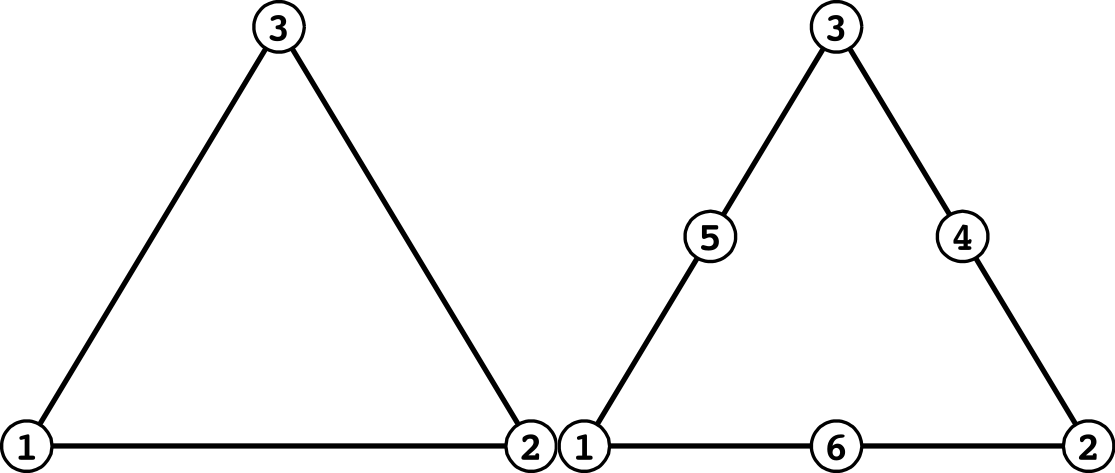
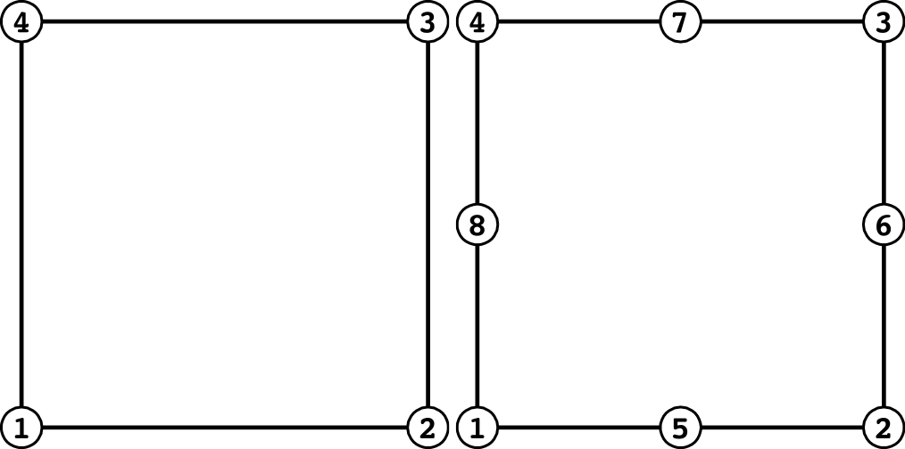
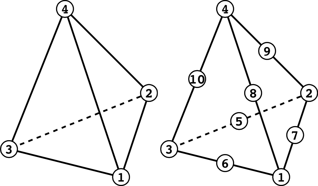
The following figures and tables show the correspondence between node ordering and face numbers in HEC-MW-format input. For the relationship between midside-node numbering in second-order elements and the ordering assumed by FrontISTR's internal shape-function implementation, see "Element Library" in the theory manual.
Line Elements

Triangular Plane Elements
| Face number | First order | Second order |
|---|---|---|
| 1 | 1 - 2 | 1 - 6 - 2 |
| 2 | 2 - 3 | 2 - 4 - 3 |
| 3 | 3 - 1 | 3 - 5 - 1 |
Quadrilateral Plane Elements
| Face number | First order | Second order |
|---|---|---|
| 1 | 1 - 2 | 1 - 5 - 2 |
| 2 | 2 - 3 | 2 - 6 - 3 |
| 3 | 3 - 4 | 3 - 7 - 4 |
| 4 | 4 - 1 | 4 - 8 - 1 |
Tetrahedral Elements
| Face number | First order | Second order |
|---|---|---|
| 1 | 1 - 2 - 3 | 1 - 7 - 2 - 5 - 3 - 6 |
| 2 | 1 - 2 - 4 | 1 - 7 - 2 - 9 - 4 - 8 |
| 3 | 2 - 3 - 4 | 2 - 5 - 3 - 10 - 4 - 9 |
| 4 | 3 - 1 - 4 | 3 - 6 - 1 - 10 - 4 - 8 |
Pentahedral Elements
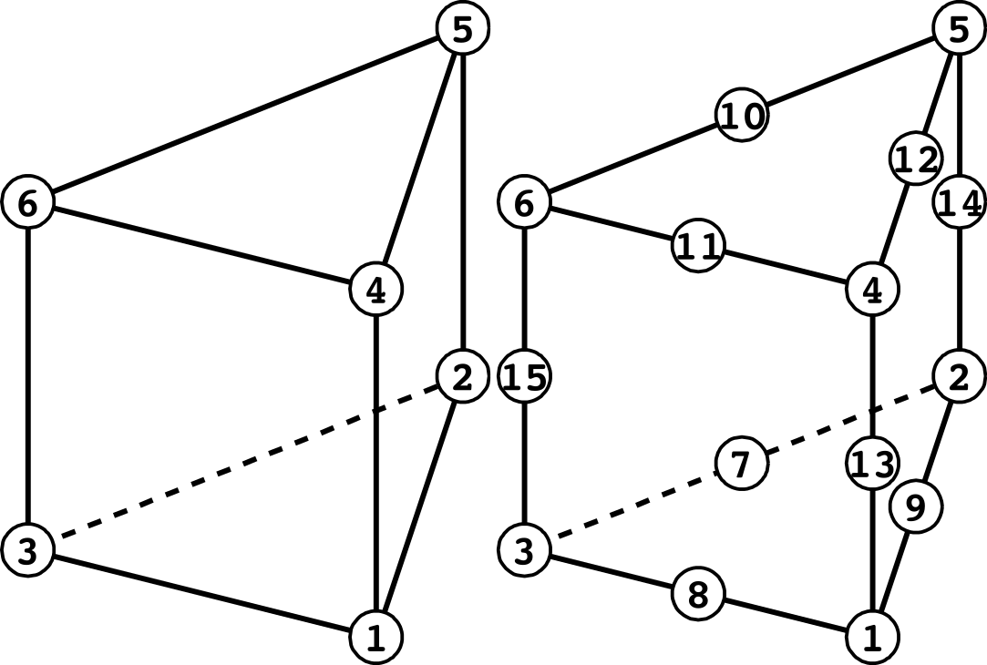
| Face number | First order | Second order |
|---|---|---|
| 1 | 1 - 2 - 3 | 1 - 9 - 2 - 7 - 3 - 8 |
| 2 | 4 - 5 - 6 | 4 - 12 - 5 - 10 - 6 - 11 |
| 3 | 1 - 2 - 5 - 4 | 1 - 9 - 2 - 14 - 5 - 12 - 4 - 13 |
| 4 | 2 - 3 - 6 - 5 | 2 - 7 - 3 - 15 - 6 - 10 - 5 - 14 |
| 5 | 3 - 1 - 4 - 6 | 3 - 8 - 1 - 13 - 4 - 11 - 6 - 15 |
Hexahedral Elements
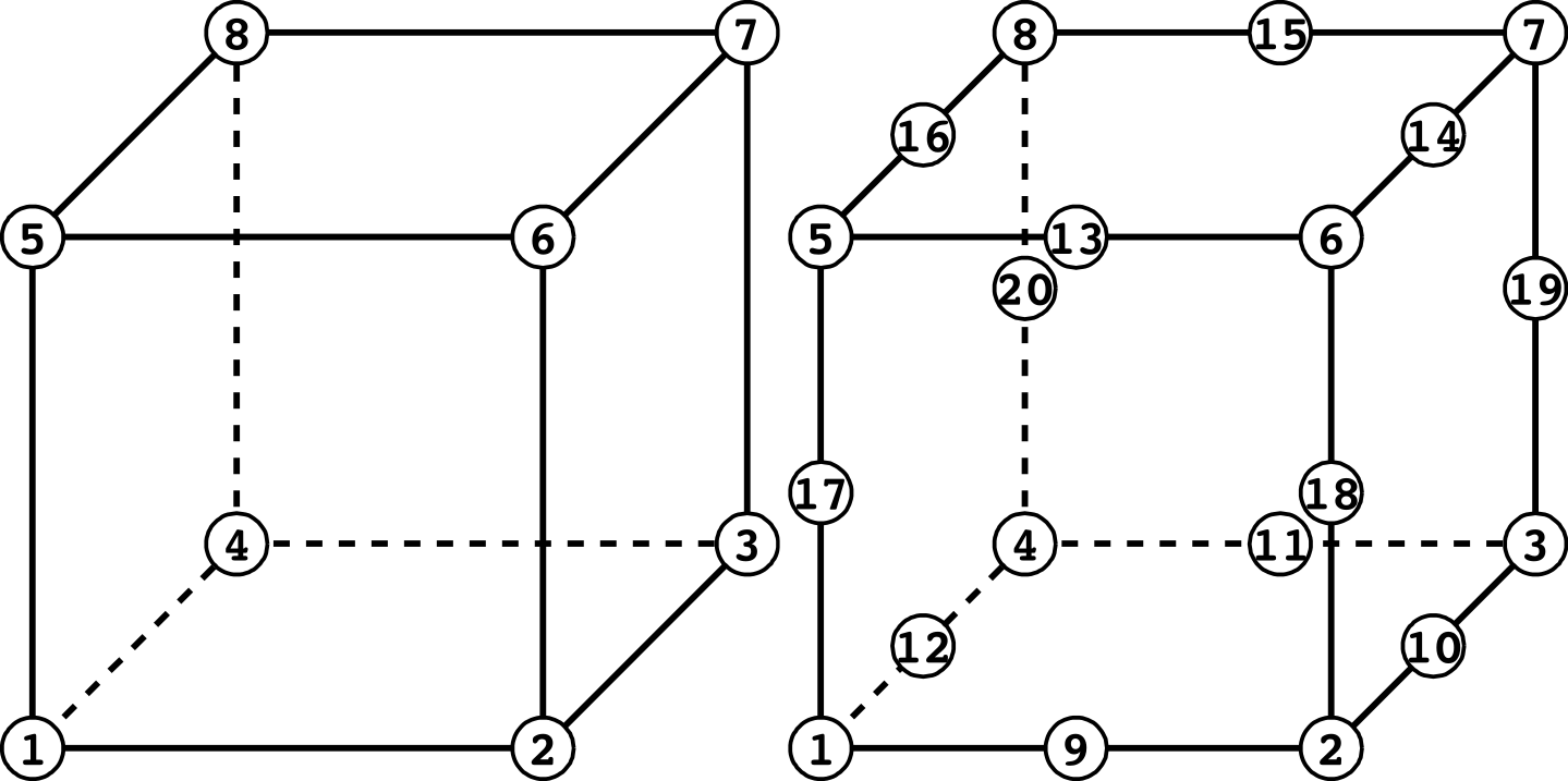
| Face number | First order | Second order |
|---|---|---|
| 1 | 1 - 2 - 3 - 4 | 1 - 9 - 2 - 10 - 3 - 11 - 4 - 12 |
| 2 | 5 - 6 - 7 - 8 | 5 - 13 - 6 - 14 - 7 - 15 - 8 - 16 |
| 3 | 1 - 2 - 6 - 5 | 1 - 9 - 2 - 18 - 6 - 13 - 5 - 17 |
| 4 | 2 - 3 - 7 - 6 | 2 - 10 - 3 - 19 - 7 - 14 - 6 - 18 |
| 5 | 3 - 4 - 8 - 7 | 3 - 11 - 4 - 20 - 8 - 15 - 7 - 19 |
| 6 | 4 - 1 - 5 - 8 | 4 - 12 - 1 - 17 - 5 - 16 - 8 - 20 |
Beam Elements

Beam Element with 3-DOF Nodes
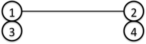
Nodes 1 and 2 have translational degrees of freedom, while nodes 3 and 4 have rotational degrees of freedom.
Triangular Shell Elements
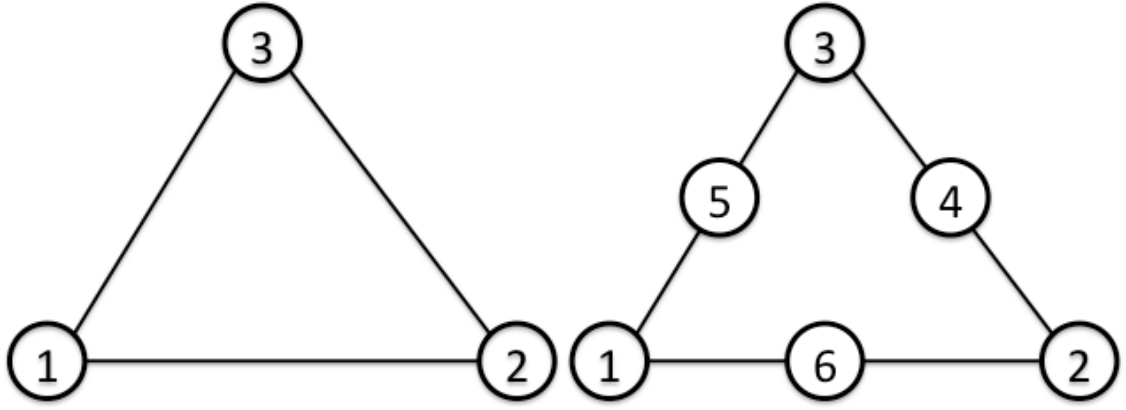
| Face number | First order | Second order |
|---|---|---|
| 1 | 1 - 2 - 3 [front] | 1 - 6 - 2 - 4 - 3 - 5 [front] |
| 2 | 3 - 2 - 1 [back] | 3 - 4 - 2 - 6 - 1 - 5 [back] |
Triangular Shell Element with 3-DOF Nodes
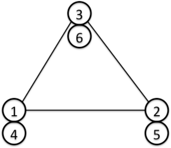
Nodes 1, 2, and 3 have translational degrees of freedom, while nodes 4, 5, and 6 have rotational degrees of freedom.
| Face number | First order |
|---|---|
| 1 | 1 - 2 - 3 [front] |
| 2 | 3 - 2 - 1 [back] |
Quadrilateral Shell Elements
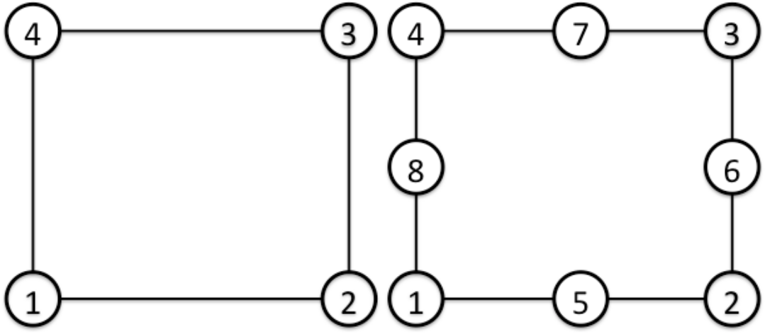
| Face number | First order | Second order |
|---|---|---|
| 1 | 1 - 2 - 3 - 4 [front] | 1 - 5 - 2 - 6 - 3 - 7 - 4 - 8 [front] |
| 2 | 4 - 3 - 2 - 1 [back] | 4 - 7 - 3 - 6 - 2 - 5 - 1 - 8 [back] |
Quadrilateral Shell Element with 3-DOF Nodes
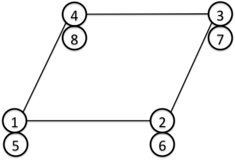
Nodes 1, 2, 3, and 4 have translational degrees of freedom, while nodes 5, 6, 7, and 8 have rotational degrees of freedom.
| Face number | First order |
|---|---|
| 1 | 1 - 2 - 3 - 4 [front] |
| 2 | 4 - 3 - 2 - 1 [back] |
Related Topics
- Element Numbering System and Shape-Function Library (Coding) — Element type numbers, shape-function library, and midside-node ordering specifications
- Material Data — Material models assigned to elements
!ELEMENT— Syntax of the element-definition keyword!SECTION(Mesh Data) — Specification of element type, material, thickness, and section!SECTION(Analysis Control Data) — Switching formulations withFORM341andFORM361